The ultimate guide to DFA (Design For Assembly)

The ultimate guide to DFA

The Concept of Assembly Assembly refers to the assembly of components into a product that can achieve the quality of a variety of products. The concept of assembly can be derived from the meaning of assembly: a) Put the components together; b) Realize the corresponding functions; c) Achieve great quality of the product. The most …

The Concept of Assembly

Assembly refers to the assembly of components into a product that can achieve the quality of a variety of products. The concept of assembly can be derived from the meaning of assembly:

a) Put the components together;

b) Realize the corresponding functions;

c) Achieve great quality of the product.

The most important thing in assembly is to achieve the product functions requirement and product quality requirement, not simply locking the screw or putting together the components. Therefore, assembly is a way to realize product function and product quality.

A product needs to go through the process of assembly before it can be manufactured and become a product. Products contain anywhere from a few to millions of parts. A stapler has dozens of parts, a cell phone has hundreds of parts, a car has tens of thousands of parts, and an airplane has more than a few million parts. Assembly is an important part of the product manufacturing process, and the assembly process has a great impact on product quality, product cost, product development cycle, and so on.

There are seven steps in the typical assembly process: 

Step-1  Place the base; The base of a part does not necessarily refer to the fixture bench, it could also be a part. For example, in the winding of the stator, relative to the enameled wire, the stator rack is a part serving as a base.
Step-2 Identify the parts; Identifying parts is also important in the assembly design process. For example, if the color of the O-ring and the parts are all black, it is difficult to recognize different parts in terms of the vision system.
3) Grab the parts; The difference between manual assembly and automated assembly needs to be considered. If the part is too soft, or too slippery, it’s difficult to grasp it for assembly.
4) Move the part to the assembly position; Parts are best assembled once in place with no interference along the way.
5) Adjust the parts to the correct position; Sometimes we need to consider adding guide features to assist the adjustment. 
6) The parts are fixed; The parts of each process are preferably fully constrained, and then proceed to the next process.
7) Inspection; This is the end of a process.

The process of manual assembly and automated assembly will be slightly different. But all assembly design requirements stem from these seven basic steps, so it’s important to remember.

Mechanical designers can generally understand the assembly process based on these seven steps, but assembly process engineers need to know more, such as the location of incoming materials, the arrangement and efficiency of fixture benches, and the specific assembly methods of production line workers. Therefore, after the mechanical engineer completes the DFA (Design for Assembly), it is necessary to discuss it with the assembly engineer.

The Difference Between A Good Assembly Design And A Bad Assembly Design

Good Assembly Process Bad Assembly Process
Parts are easy to recognize Parts are difficult to recognize
Parts are easy to grab and placed in the right position Parts are difficult to grab and easy to fall
Parts can be easily adjusted to the right position Parts need workers to keep adjusting in order to find the right position 
Parts have a single right assembly point Parts can be assembled at multiple assembly points and it’s difficult to tell which point is right. Parts can be even assembled at the wrong point. 
Very few screws. Parts can be assembled quickly. Many screws and many types of screws.
No tool or fixture is needed in the assembly process Tools or fixture is needed in the assembly process
Very few adjustment is needed in the assembly process Consistent adjustments are needed in the assembly process
The assembly process is easy to study execute The assembly process is difficult to study and execute

Design For Assembly (DFA)

Design for assembly (DFA) refers to making the product have good assembly ability in the product design stage, ensuring a simple assembly process, high assembly efficiency, high assembly quality, low assembly defect rate, and low assembly cost. The purpose of doing Design for assembly (DFA) is to figure out the best assembly process of every single component or part by optimizing the product design. 
 
Design for Assembly (DFA) should be considered at all stages of the design process, especially in the early stages of design. As the design team considers multiple options, the ease of assembly of the product or part needs to be carefully considered. Design teams need a DFA tool to efficiently analyze the ease of assembly of a product or part. Design tools should provide results quickly, and be simple and easy to operate. It shall ensure the coherence and completeness of the product assembly feasibility assessment. It should also eliminate subjective judgment in assembly design, allow free association, allow easy comparison of different designs, ensure scientific evaluation of the final solution, determine the scope of assembly problems, and be able to provide multiple alternatives to simplify product mechanical design, thereby reducing the cost of manufacturing and assembly. Through the application of DFA, the communication between manufacturing and design can be improved, and the ideas, reasoning, and decisions made during the product design process can be well documented for future reference.
 
The DFA approach attempts to achieve these goals in the following ways:
① Provide a tool for those designers or teams to ensure that their consideration of product complexity and assembly occurs only at the initial design stage. This can avoid the risk that the designer only focuses on the function of the product at the initial stage of design without sufficient consideration of the cost and competitiveness of the product.
② Guide designers or design teams to simplify products, thereby reducing assembly costs and parts costs.
③ Collect the experience data usually owned by experienced design engineers, organize these data, and provide them to inexperienced design engineers to study.

④ Establish a database that contains assembly time and cost elements under various design states and production conditions.

Through design for assembly (DFA), product development can achieve the following goals:

① Simplify the product assembly process.
②Reduce product assembly time.
③Reduce product assembly errors.
④Reduce product design modifications.
⑤Reduce product assembly costs.
⑥Reduce product assembly defect rate.
⑦Improve product assembly quality.
⑧Improve product assembly efficiency.
⑨Increase the utilization of existing equipment.

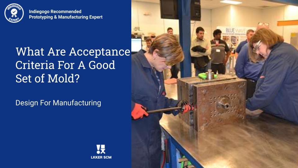
What are the acceptance criteria for a good set of molds?

What are the acceptance criteria for a good set of molds

01 Mold appearance 1. The content of the mold nameplate is complete, the characters are clear, and the arrangement is neat. 2. The nameplate should be fixed on the mold foot near the template and the reference angle. The nameplate is reliable and not easy to peel off. 3. The cooling water nozzle should be …

01 Mold appearance

1. The content of the mold nameplate is complete, the characters are clear, and the arrangement is neat.

2. The nameplate should be fixed on the mold foot near the template and the reference angle. The nameplate is reliable and not easy to peel off.

3. The cooling water nozzle should be made of plastic block water nozzle, if the customer requires otherwise, please follow the requirements.

4. The cooling water nozzle should not protrude from the surface of the mold base.

5. The cooling water nozzle needs to be processed with a counterbore. The counterbore diameter is 25mm, 30mm, and 35mm. The orifice is chamfered and the chamfering should be the same.

6. The cooling water nozzle should be marked for entry and exit.

7. Mark English characters and numbers should be greater than 5/6, and the position should be 10mm directly below the tap. The handwriting should be clear, beautiful, neat, and evenly spaced.

8. Mold accessories should not affect the hoisting and storage of the mold. During installation, there are exposed oil cylinders, faucets, pre-reset mechanisms, etc., which should be protected by supporting legs.

9. The mounting of the support leg should be fixed on the mold base with screws passing through the support leg, and the excessively long support leg can be fastened to the mold base with a machined external threaded column.

10. The size of the ejector hole of the mold should meet the requirements of the specified injection molding machine. Except for small molds, one center cannot be used for ejection.

11. The positioning ring should be fixed and reliable. The diameter of the ring is 100mm and 250mm. The positioning ring is 10-20mm higher than the bottom plate. Unless otherwise requested by customers.

12. The overall dimensions of the mold should meet the requirements of the designated injection molding machine.

13. For molds with orientation requirements, an arrow should be used to indicate the installation directly on the front template or the rear template, and there should be “UP” next to the arrow. The arrow and text are both yellow and the height of the font is 50mm.

14. The surface of the mold base should not have pits, rust marks, redundant rings, water vapor in and out, oil holes, etc., and defects that affect the appearance.

15. Moulds should be easy to hoist and transport. Mold parts must not be disassembled during hoisting. Lifting rings must not interfere with faucets, cylinders, pre-reset rods, etc.

02 Mold material and hardness

1. The mold base should be a standard mold base that meets the standard.

2. The material of mold forming parts and gating system (core, movable and fixed mold insert, movable insert, diversion cone, pushrod, sprue sleeve) shall be made of materials with performance higher than 40Cr.
3. When molding plastics that are corrosive to the mold, the molded parts should be made of corrosion-resistant materials, or the molding surface should take anti-corrosion measures.
4. The hardness of the molded parts should not be lower than 50HRC, or the hardness of the surface hardening treatment should be higher than 600HV.

03 Eject, reset, pull out the core, take out

1. The ejection should be smooth, free of jamming, and no abnormal sound.

2. The inclined top surface should be polished, and the inclined top surface is lower than the core surface.

3. The sliding parts should be provided with an oil groove, and the surface needs to be nitrided, and the surface hardness after treatment is HV700 or higher.

4. All ejector rods should have stop-rotation positioning, and each ejector rod should be numbered.

5. The ejection distance should be limited by a limit block

6. Standard parts should be used for the return spring, and both ends of the spring should not be polished or cut off.

7. Slider and core-pulling should have stroke limit, small slide is limited by spring, if spring is inconvenient to install, corrugated screw can be used; cylinder core-pulling must have a stroke switch.

8. Generally, inclined guide posts are used for core pulling of the slider, and the angle of the inclined guide post should be 2°~3° smaller than the angle of the locking surface of the slider. If the stroke of the slider is too long, the oil cylinder should be used for drawing.

9. When the end surface of the core-pulling forming part of the cylinder is covered, the cylinder should be equipped with a self-locking mechanism.

10. There should be a wear plate under the large sliding block with a width of more than 150 mm. The material of the wear plate should be T8A. The hardness after heat treatment is HRC50~55. The wear plate is 0.05~0.1 mm higher than the large surface. Open the oil tank.

11. The ejector rod should not move up and down.

12. Add barbs to the top rod, and the direction of the barbs should be consistent, so that the barbs are easy to remove from the product.

13. The clearance between the ejector pin hole and the ejector pin, the length of the sealing section, and the surface roughness of the ejector pin hole should be in accordance with the requirements of the relevant enterprise standards.

14. The product should be convenient for the operator to remove it.

15. When the product is ejected, it is easy to follow the inclined top, and the top rod should be grooved or etched.

16. The top block fixed on the top rod should be firm and reliable, the non-formed parts around the circumference should be processed with a 3°~5° slope, and the lower periphery should be chamfered.

17. There should be no iron filings in the oil passage hole on the mold base.

18. The end face of the return rod is flat and there is no spot welding. No gasket at the bottom of the embryo head, spot welding.

19. The gate plate of the three-plate mold slides smoothly, and the gate plate is easy to open.

20. Three-plate mold limit rods should be arranged on both sides of the mold installation direction, or pull plates should be added to the mold base to prevent the limit rods from interfering with the operator.

21. The oil circuit and air passage should be smooth, and the hydraulic ejector reset should be in place.

22. An exhaust port should be opened at the bottom of the guide sleeve.

23. There should be no clearance for the positioning pin installation.

04 Cooling and heating system

1. The cooling or heating system should be fully unblocked.

2. The seal should be reliable, the system should not leak under the pressure of 0.5MPa, and it is easy to check and repair.

3. The size and shape of the sealing groove opened on the mold base should meet the requirements of relevant standards.

4. Grease should be applied to the sealing ring when it is placed, and it should be higher than the surface of the mold base after it is placed.

5. Water and oil flow channel separators should be made of materials that are not easily corroded.

6. The front and back molds should use a centralized water supply.

05 Gating system

1. The gate setting should not affect the appearance of the product and satisfy the product assembly.

2. The runner section and length should be reasonably designed, and the process should be shortened as much as possible under the premise of ensuring the forming quality, and the cross-sectional area should be reduced to shorten the filling and cooling time. At the same time, the plastic loss of the pouring system should be the least.

3. The partial cross-section of the three-plate mold runner at the back of the front mold plate should be trapezoidal or semicircular.

4. The three-plate mold has a material breaker on the gate plate, the diameter of the gate entrance should be less than 3 mm, and the ball head has a 3 mm deep step recessed into the gate plate.

5. The ball end pull rod should be reliably fixed, can be pressed under the positioning ring, can be fixed with headless screws, or can be pressed with a pressure plate.

6. Gates and runners should be machined according to the size requirements of the drawings, and manual grinding and polishing machines are not allowed.

7. The pointed gate should be in accordance with the requirements of the specification.

8. There should be an extension at the front end of the runner as a cold slug hole.

9. The Z-shaped inverted buckle of the pulling rod should have a smooth transition.

10. The runner on the parting surface should be round, and the front and rear molds cannot be misaligned.

11. The latent gate on the ejector rod should have no surface shrinkage.

12. The diameter and depth of the cold slug hole for transparent products should meet the design standards.

13. The handle is easy to remove, there is no gate mark on the appearance of the product, and there is no residual handle at the product assembly.

14. For the curved hook latent gate, the two parts of the insert should be nitrided, and the surface hardness can reach HV700.

06 Hot runner system

1. The wiring layout of the hot runner should be reasonable for easy maintenance, and the wiring numbers should be a one-to-one correspondence.

2. The hot runner should be tested for safety, and the insulation resistance to the ground should be greater than 2MW.

3. Standard parts should be adopted for temperature control cabinets, hot nozzle, and hot runner.

4. The main flow port sleeve is connected with the hot runner with threads, and the bottom surface is in contact with the hot runner for sealing.

5. The hot runner is in good contact with the heating plate or heating rod, and the heating plate is fixed with screws or studs, and the surface fits well.

6. The J-type thermocouple should be used and matched with the temperature control meter.

7. Each group of heating elements should be controlled by thermocouples, and the position of the thermocouples should be reasonably arranged.

8. The nozzle should meet the design requirements.

9. The hot runner should be reliably positioned, at least two positioning pins, or fixed with screws.

10. There should be an insulation pad between the hot runner and the template.

11. The error between the set temperature of the temperature control meter and the actual display temperature should be less than ±5°C, and the temperature control should be sensitive.

12. The cavity and nozzle installation hole should pass through.

13. The hot runner wiring should be bundled and covered with a pressure plate.

14. There are two sockets of the same specification, which should be clearly marked.

15. The control line should be sheathed and not damaged.

16. The structure of the temperature control cabinet is reliable, and the screws are not loose.

17. The socket is installed on the bakelite and cannot exceed the maximum size of the template.

18. The wires must not be exposed outside the mold.

19. There should be rounded transitions at all the places where the hot runner or template is in contact with the wires.

20. Before the template is assembled, there is no open circuit or short circuit in all circuits.

21. All wiring should be connected correctly, with good insulation performance.

22. After the template is installed and clamped, all circuits should be checked again with a multimeter.

08 Injection molding production process

1. The mold should have the stability of injection molding production and the repeatability of process parameter adjustment within the range of normal injection molding process conditions.

2. The injection pressure during mold injection production should generally be less than 85% of the injection molding machine’s rated maximum injection pressure.

3. The injection speed during the injection molding production of the mold, the injection speed of the three-quarter stroke is not less than 10% of the rated maximum injection speed or more than 90% of the rated maximum injection speed.

4. The holding pressure during mold injection production should generally be less than 85% of the actual maximum injection pressure.

5. The clamping force of the mold during injection molding production should be less than 90% of the rated clamping force of the applicable model.

6. During the injection molding production process, the product and nozzle material should be taken out easily and safely (the time is generally not more than 2 seconds each).

7. For molds with inserts, the inserts are easy to install and the inserts are fixed reliably during production.

09 Packing and shipping

1. The mold cavity should be cleaned and sprayed with anti-rust oil.

2. The sliding parts should be lubricated.

3. The inlet of the sprue bushing should be sealed with grease.

4. The mold should be equipped with a clamping piece, and the specifications meet the design requirements.

5. Spare parts and wearing parts should be complete, with a detailed list and the name of the supplier.

6. Sealing measures should be taken to prevent foreign matter from entering the mold water, liquid, gas, and electrical inlets and outlets.

7. Spray paint on the outer surface of the mold, as required by the customer.

8. Molds should be packaged in moisture-proof, waterproof, and bump-proof packaging, as required by customers.

9. Mold product drawings, structural drawings, cooling, and heating system drawings, hot runner drawings, spare parts, and mold material supplier details, operating instructions, mold test report, factory inspection certificate, and electronic documents should all be complete.

Learn More:

1.  LKK Mold Making Service

2.  Mold Assembly Process Video

3.  Mold Making Process Video 

4.  Mold T0 Sample, T1 Sample Video -Sweeping Robot

Car Dashboard 3D Mold design

Car Dashboard 3D Mold design

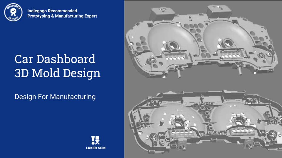
Mold Making is an important step in product development. Car Dashboard mold design case study to understand how to conduct mold design.

The car dashboard photo is shown below. The overall dimension of the product is 343.40 mm x 167.13 mm x 48.01 mm, the average thickness of the plastic part is 2.00 mm, the material of the plastic part is PP TD40, the shrinkage rate is 1.010, and the quality of the plastic part is 208.88 grams. The technical requirements for plastic parts are that there must be no defects such as peaks, unfulfilled injection molding, flow lines, pores, warpage deformation, silver streaks, cold materials, jet lines, etc.

This is the internal bracket of the dashboard of a Japanese car. As can be seen from the photo above, the mechanical design of the plastic part is a flat complex shell, the dynamic and fixed mold has many bone positions and column positions, the size is large, and the mold is a large mold. The plastic part is made of PP td40. Calcium carbonate filler is added to the material, mainly to increase the rigidity and fatigue resistance of the plastic part and play the role of shock absorption.

Due to the large size of plastic parts, the cavity ranking of mold design is 1 out of 1, the injection molding machine is 220 tons.

Mold design stylebook is an important document of mold design. It stipulates the number of cavities, the way of plastic injection, the brand grade of mold core steel and standard parts, mold life, model of the injection molding machine, and injection cycle, which are the basis of mold design.

Here are the most common terms of molds:

Mold review meeting; Mold unloading inclined portion; Mold locking force; T0 sample; Dimension; Gate sleeve spherical surface;

The mold review meeting is to review the problem points and improvement countermeasures of product and mold mechanical design and determine the parting surface, ejection mode, and gate of the mold. All review contents shall be marked in the product drawing and written in the mold stylebook with red and blue pencil or pencil. After the review, fill in the relevant review records, seal on the drawings, and sign for confirmation by both parties.

The Importance of Mold Design Positioning Systems

The guide pin and sleeve of the mold are the primary positionings of the entire mold. Because there is a gap of 0.01-0.03mm between the guide pin and the hole of the guide sleeve, it is obviously not enough to rely only on the guide pin and guide sleeve for positioning large molds. Four conical positioning parts are designed on the four sides of the mold block. The three-level positioning refers to the precise positioning of the design tiger mouth on the mold core, which mainly protects the accurate positioning of the inserting surface of the mold.

Two three-level positioning systems are designed for the mold of the car dashboard. The first is to design the tiger mouth positioning around the guide pin and guide sleeve of the mold block. The second is to design the tiger mouth positioning at the four corners of the front and rear of the mold core. The design of so many positioning mainly takes into account that the car dashboard mold belongs to a large mold and has the design configuration of mold core eccentricity. Therefore, it is very important to design effective positioning and guidance. In order to balance the mold locking force, a balance weight is designed on the parting surface.

The exhausting slot of a large injection mold is very important. The way of exhausting-slot must be analyzed in advance, focusing on the areas easy to trap gas, and the exhaust must be designed on the mold drawing. An exhaust shall also be ground at the edge of the insert to facilitate injection mold filling.

Car Dashboard Mold Design Highlight

Due to the large size of the plastic part, the cavity is arranged one out and one eccentrically. The mold block is the standard mold block CH5565. The front and rear of the mold cores are positioned and locked by extrusion blocks. Positioning pins are added between the B plate of the moving mold, square iron, and bottom plate to maintain the rigidity of the mold.

The area of plastic parts is large and the molten plastic process is long, so the design of the gating system is very essential. Considering that there are many bones and holes in plastic parts, there are many factors affecting the flow of molten plastic and large filling resistance. Therefore, the gating system is designed with a 3-point latent gate, which is located on the same side of the plastic part. The runner pull pin is designed with a tapered pull pin to facilitate the manipulator to grasp the material at the water intake. 

The ejector system of plastic parts adopts an ejector pin and cylinder ejector. In order to make the ejection system smooth, some innovative designs have been made. The middle support guide pin is designed, which is guided by graphite middle support. The top of the middle support guide pin is fixed on the back of plate B with locating pins, and the bottom is fixed on the moving mold plate with screws. The design of the middle support guide pin has the best guiding performance and overcomes the disadvantage of the poor verticality between the traditional middle support guide pin and the thimble plate.

At the same time, the middle support guide pin can also act as a support head. For the convenience of mold installation, M10 threaded holes are designed on the end face of the return needle to tighten the thimble plate. At the same time, limit screws are designed on the thimble plate, and positioning pins are designed on the top of the support heads. All thimbles adopt Japanese Misumi high-speed steel thimble SKH51.

The cooling system design of the mold is shown below. The front and rear molds are designed with direct water transportation and ponds to effectively ensure the cooling effect.

The total type of mold parts is more than 40 and the number is nearly 100, so the reasonable identification of parts is particularly important for design and production.

Firstly, according to the role of each part in the mold, the parts can be divided into four categories: template, cavity, mechanical parts, and standard parts. The template constitutes the matrix of the mold, the cavity is the core of the mold, and the mechanical parts and standard parts are the auxiliaries of the mold.

Here are numbers and details of parts specified in the mold drawings: 

How To Manage Parts Design In 3D Drawings

The drawing number of parts is prepared on this basis and expressed by 3 Arabic numerals. After determining the part drawing number coding rules, similar parts can be set in different layers during 3D parting. The drawing numbers are arranged clockwise or counterclockwise on the assembly drawing:
1) The formwork is arranged in M1, M2, M3… Order from the fixing plate of the fixed mold to the fixing plate of the dynamic mold;
2) Cavity parts (fixed mold) are arranged in the order of V1, V2, V3;
3) Core parts (dynamic mold) are arranged in the order of C1, C2, C3;
4) Sliding block parts are arranged in sequence of S1, S2, S3;
5) Inclined roof parts are arranged in order of L1, L2, L3;
6) The auxiliary parts of the fixed mold are arranged in the order of A1, A2, A3;
7) The auxiliary parts of the dynamic mold are arranged in the order of B1, B2, B3;

The specific meaning of the part number is: the first letter indicates the category of parts, and the following number is the sequence number of parts. This classification drawing number is simple to write and can achieve the purpose of classified management and classified processing of parts. In the specific mold design, it is necessary to ensure that the part drawing numbers of 2D and 3D drawings of the mold are consistent, and the drawings are consistent with the physical mold parts and even write on the mold parts when necessary, so as to facilitate the maintenance and replacement of the mold parts in the future.

When the mold is changed, the number of parts will change. For modified parts, add A, B, C, D… After the drawing number to indicate different versions. For new parts, write a new drawing number according to the rules. For all newly added and modified drawings, the drawing date on the drawings shall be updated to facilitate the production management.

Learn More:

1. LKK Mold Making Service

2. Mold Assembly Process Video

3. Mold Making Process Video 

4. Mold T0 Sample, T1 Sample Video -Sweeping Robot